Related
Table of content
The Build Custom Graph relies on user-made blueprint to create clusters from scratch. It comes with two blueprint base classes that can be extended and used to create nodes & edges in a very straightforward yet flexible way.

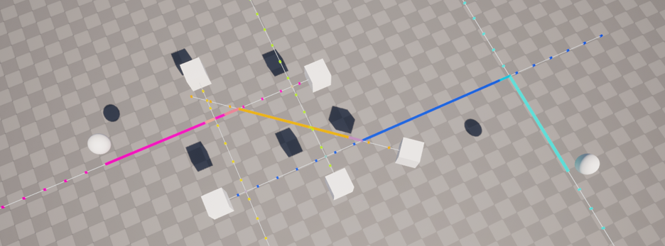
It’s highly recommended to look at the example project’ Custom Graph example – it’s simple enough and covers 100% of the available features for this node.
Properties
| Property | Description |
|---|---|
| Mode | The selected mode drives how and which actors will be made available to the custom graph builder. - Owner only forwards the PCG Component’ owner.- Actor References takes point dataset coming from a GetActorData node and forwards any actor reference that successfully resolve to a world actor. |
| Actor Reference Attribute | When using Actor Reference mode, this is the name of the attribute that contains actor references paths. |
| Builder | User-made custom graph builder object. |
| Mute Unprocessed Settings Warning | This quiets the warning regarding invalid settings (e.g settings that don’t have enough nodes) |
| Cluster Output Settings | See Working with Clusters - Cluster Output Settings. |
Note that the PCG Graph will work with a copy of the selected builder, not the instance that exists within the setting panel. In case you’re doing fancy stuff in the constructor, which you probably shouldn’t, keep in mind only public blueprint variables will be copied from it.
Workflow

The custom graph workflow is made out of two pieces. The main one, Custom Graph Builder, drives how many graphs will be generated; The other, Custom Graph Settings, is a data/settings holder that is responsible for creating edges & updating individual nodes’ PCG points.
- First, create a new blueprint inheriting from
[PCGEx] Custom Graph Settings. - Override the
InitializeSettings,BuildGraphandUpdateNodePoint.-
InitializeSettingsis where you confirm the settings are valid, and optionally reserve some memory for your graph. -
BuildGraphis where you will add edges to the graph. -
UpdateNodePointis where you will set individual node' PCG point properties.
-
- Next, create a new blueprint, inheriting from
[PCGEx] Custom Graph Builder. - Override
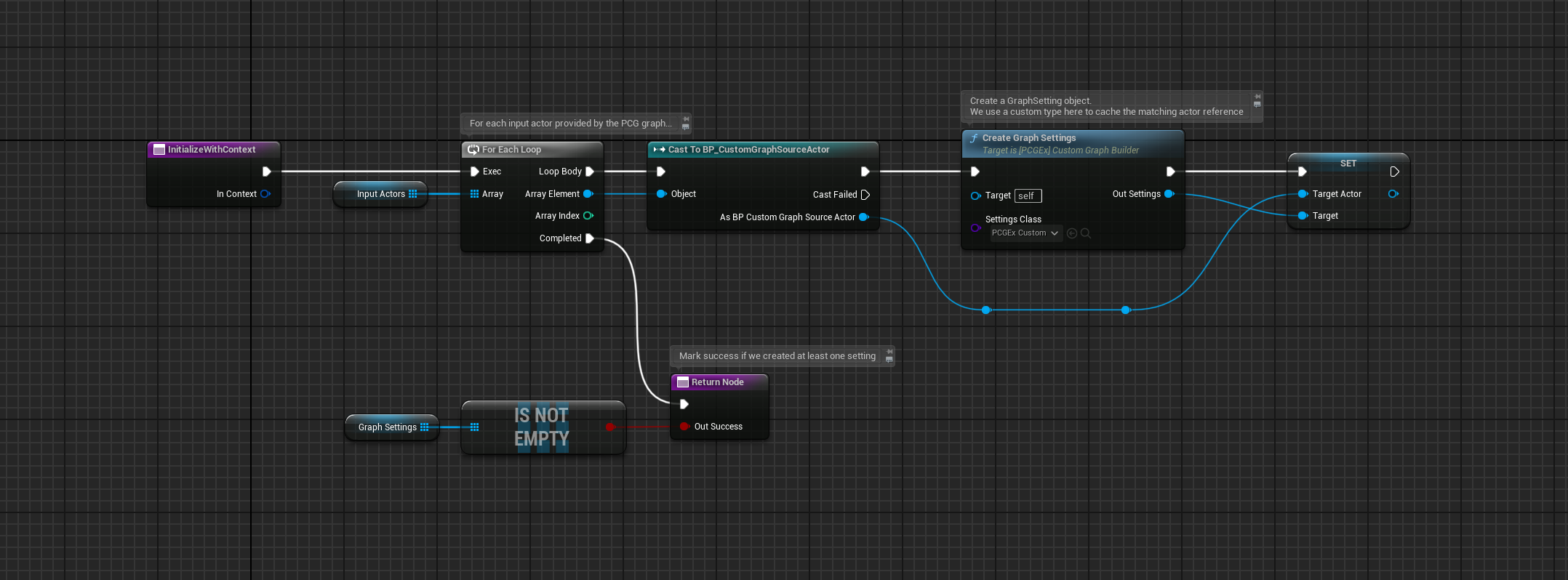
InitializeWithContext. This is where you will create "settings" objects using the internalCreateSettingsmethod and the class created before. Each unique settings represent a single graph, that you will populate as you see fit.
Only
InitializeWithContextis executed on the main thread, all other methods are called from asynchronous, multi-threaded places. If you need custom initialization behavior that is guaranteed to run on the main thread, implement your own method and call it on the setting object after usingCreateSettingsduring builder’ initialization.
Order of operations
- First,
InitializeSettingswill be called on the main builder instance. - Then, for each graph settings registered during initialization, individual Settings objects will have their
BuildGraphmethod called. This is where you add edges. Points will be automatically created based on the IDs you use to register edges. - Finally, each individual Settings will have its
UpdateNodePointmethod called once per node created. Since this part is heavily multi-threaded, there is no call order guarantee. - That’s it!
Custom Graph Builder
The custom graph builder is only responsible for creating Custom Graph Settings, and forwarding them with actor references provided by the host PCG node.
The execution flow is controlled by the latter, so it’s only important to implement InitializeSettings.
This object has an internal read-only array, InputActors, which is populated by the host PCG node based on its selected Mode. It is assumed that you either use custom component or blueprint that store custom data from which you will be building custom graphs, so you can fetch & filter more custom components from these actors references.
You may also access another internal read-only array, GraphSettings, which contains all settings created using the CreateSettings method.
InitializeWithContext
–
You may override BuildGraph if you need to do some sort of pre-processing of the settings at the builder level, but it’s highly unlikely that you ever need to do so. The multi-threaded nature of this node means that there is no guarantee that other concurrent graphs are properly initialized at this point, so everything should be kept in silos.
Custom Graph Settings
The custom graph settings are holding data & providing a handy way to cache per-graph data mapping, as well as a streamlined way to create edges and update graph PCG points.
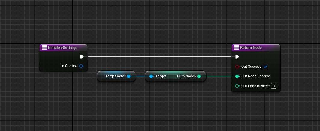
InitializeSettings
 Example where initialization uses a property on an actor to drive the number of node for these settings. Note that there is no relationship whatsoever between input actors and graph, they’re just a convenience thing.
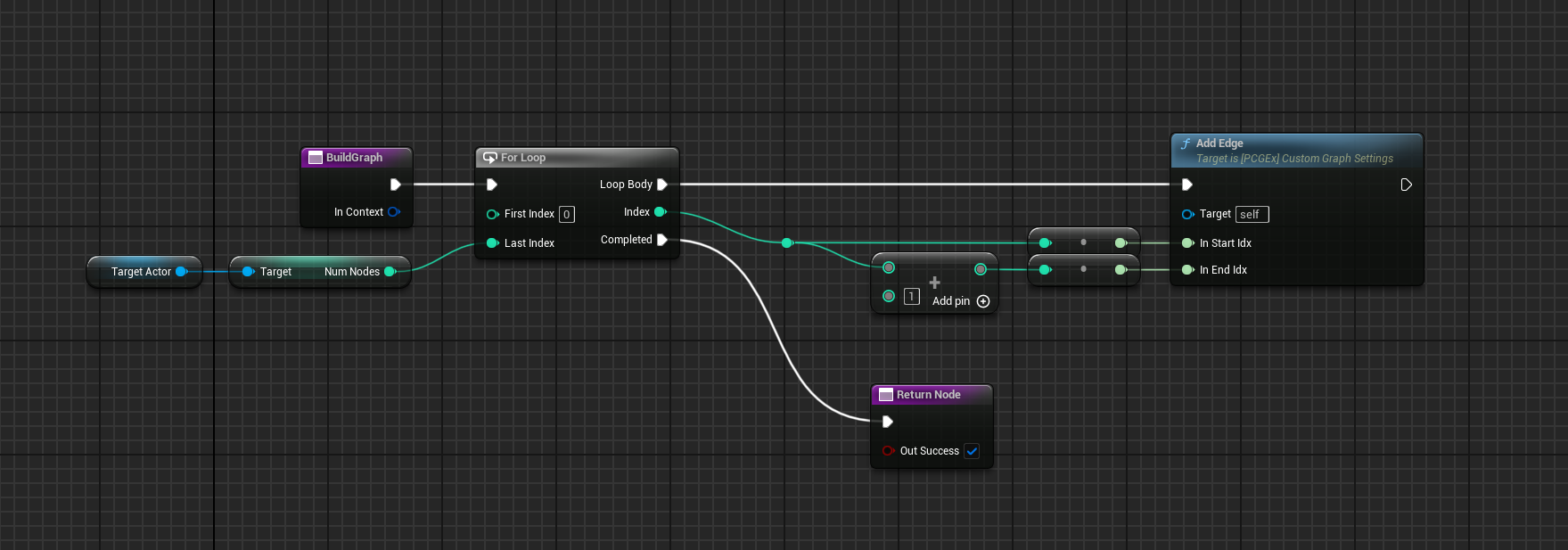
BuildGraph
BuildGraph is where you call AddEdge appropriately. The method takes two int64 IDs – those can be point index, or whatever you see fit. These IDs will be passed to UpdateNodePoint later on; along with the internal point index assocaited with it.
RemoveEdge is also available if you want to remove a previously added edge.
Custom Graph uses per-node IDs instead of indices so that you can build a graph as you discover connections. It comes at the cost of a slight overhead, but it’s much more flexible that way.
You don’t have to worry about duplicate/directed edges, the graph system uses an unsigned hash under the hood, so
A -> BandB -> Arefer to the same edge.
 Example where a straight line of edges is created by using a simple loop index.
UpdateNodePoint
 Example where a point position is oriented forward in space using an actor’ transform, and setting the point Color from a variable on the actor.
