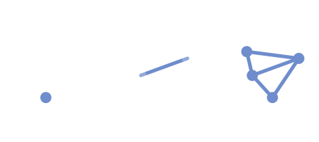
One of the main focus of PCGEx is working with Clusters : vtx & edge-based “graph” structures. They’re akin to a mesh without faces: a bunch of vertices connected by a bunch of edges.

PCGEx leverage PCG’ point data as data holders in order to enable easy tweaking and manipulation of edge/vertice data using existing vanilla nodes. In short, a graph is represented by at least two separate set of points: the first, Vtx represent individual vertices; others, Edges, represent interconnected clusters.
Edges points stores the indices of their start and end point in the matching Vtx group.
Because of that approach, nodes that work with graph require
VtxandEdgesas separate inputs. Data Tags are used to mark which edges match which vertices, so you will see additional tags appear on your data, formatted asPCGEx/XXX.
Rule of thumb : If you manually alter (as in add or remove points) the content of a
VtxorEdgescreated by a PCGEx Node, make sure to use theSanitize Clusters node before using them as inputs for other PCGEx nodes.
Checklist
Packed data
The PCGEx/VtxEndpoint attribute first 32 bits are that Vtx unique ID from the cluster perspective, while the last 32 bits contains the number of Edges this Vtx is connected to. It makes up the identity of the Vtx. Alternatively, Edges have a PCGEx/EdgeEndpoints attribute whose first 32 bits matches their start’ Vtx unique ID, and the last 32 bits are the edge’ end Vtx unique ID.
Put together, this data is used to rebuild clusters in memory. If you manually alter (read : using native nodes) the number of points in either Vtx or Edges dataset, make sure to use Sanitize Clusters to restore the coherence of these attributes.
Rule of thumb : The only information that matter on
Edgesfor clusters is theirstartandendattribute. Their position in space is ignored so feel free to use those points if they can be relevant to you.
Clusters
In PCGEx terms, a cluster is “a set of Vtx and Edges that are interconnected in a finite way” – in other words, there is a guaranteed way inside a cluster that a path can be found between any Vtx to any other Vtx when passing through Edges.
A graph usually has a single set of vertices, but will output as many edge datasets as there are clusters. These will be then rebuilt inside the nodes to be processed.

If you find yourself with unexpected disconnections that ruin your pathfinding, check out
Connect Clusters or
Fuse Clusters.
Cluster Output Settings
This group of settings is present on all PCGEx nodes that output cluster data. They’re used to prune undesired ouputs and include a few very specific optimization options.
| Property | Description |
|---|---|
| Edge Position | If enabled, edge point’ position will be the result of that value used as a lerp between its start and end Vtx point. |
| Pruning | |
| Min Vtx Count | If enabled, only ouputs clusters that have more ( > ) Vtx than the specified number. |
| Max Vtx Count | If enabled, only ouputs clusters that have less ( < ) Vtx than the specified number. |
| Min Edge Count | If enabled, only ouputs clusters that have more ( > ) Edge than the specified number. |
| Max Edge Count | If enabled, only ouputs clusters that have less ( < ) Edge than the specified number. |
| Misc | |
| Refresh Edge Seed | If enabled, Edge points gets a fresh seed. |
| Build and Cache Cluster | If enabled, pre-build and cache cluster along with the point data. This has a slight memory cost associated to it, but can offer tremendous performance improvement. If disabled, cluster processors that comes down the line have to rebuild clusters from point data, which is very costly as they are also tested for errors and possible disconnections in the process. |
| Expand Clusters | If enabled, also build & cache another layer of cache data. This can have a significant memory cost, as well as a minimal performance overhead, but can greatly improve certain specific operations down the line. |
Important Notes
Altering
PCGEx/VtxEndpoints,PCGEx/ClusterIdvoids the guarantee that PCGEx nodes will work as expected.
The
UIDused for the tagging is NOT deterministic, and will change at each execution of the graph, and for each node. It is used under the hood only, and should not be edited, nor relied upon for any kind of tag-related operations. For the same reason, if you create custom tags starting withPCGEx/, it will break existing vtx/edge associations.
Because of the reliance on the tagging system, if you editVtxandEdgesbefore using them with a PCGEx node, make sure tags are preserved.
I’m working on more robust ways to associate the data other than tags, but sadly tagging is the most bulletproof and reliable method I found. Underlying data types are always at the risk of not being preserved if they’re not properly duplicated, which can happen in earlier/experimental version of PCG that this plugin is supporting.