Related
Table of content
The Connect Clusters creates “bridge” edges between all input clusters and outputs a single bigger one as a result.
Properties
| Property | Description |
|---|---|
| Bridge Method | The method that will be used to identify and create bridges between clusters. |
Note that no matter what method is selected, a bridge will always connect the two closest points between two clusters. The chosen method only drives which cluster is connected to which other cluster.
Bridge Methods
| Method | Description |
|---|---|
 |
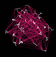
Delaunay When using this method, each cluster is abstracted into a single bounding box that encapsulates all its vertices. A 3D Delaunay is generated using each bounding box center as an input, and the resulting delaunay edges are used as bridges. |
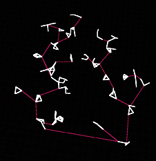 |
Least Edges When using this method, the algorithm will generate the least possible amount of bridge in order to connect all the clusters together. Careful because it can easily look like a minimum spanning tree, but it’s not. |
 |
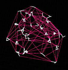
Most Edges When using this method, the algorithm will create a bridge from each cluster to every other cluster. |
Projection Settings
The projection settings control how the point position is translated to a 2D space before the graph is computed; and how this projection will translate back to the original space, if relevant.
| Property | Description |
|---|---|
| Projection Normal | Normal vector of the plane used for projection. By default, the projection plan normal is Up; so the graph is computed over the X Y plane. |
| Local Projection Normal | If enabled, uses a per-point projection vector. |
| Local Normal | Attribute ti read normal from, |
Local projection normal is very powerful but can also be very clunky to use – it’s very easy to end up with singularities that will prevent the graph from being properly computed.
Carry Over Settings
“Carry over” settings lets you pick-and-choose which attributes & tags carry over to the new data.
| Property | Description |
|---|---|
| Preserve Attributes Default Value | If enabled, the node will attempt to create attributes on the data in a way that preserve the original, underlying default value of the attribute. This can be critical in order to identify which data originally belonged to which, as well as properly initializing flags to a desirable default. |
| Attributes | Lets you pick and choose which attributes to keep or dismiss. |
| Tags | Lets you pick and choose which attributes to keep or dismiss. |
Both Attributes & Tags share the same string-based filters.
Note that the filters look for a single valid match amongst the list; you cannot create and/or conditions.
Filter Details
| Property | Description |
|---|---|
| Filter Mode | Chooses how the filter operates. - All let everything pass.- Exclude filters out the result of the filter.- Include only allows the items that pass the filters. |
| Matches | Lets you define a list of checks pairs: a string value, and a Match Mode. |
| Comma Separated Names | Easy to override, lets you specify a list of comma-separated names. The only caveat is that you can only pick a unique match mode used for each entry. |
| Comma Separated Names Filter | Which filter will be used along the Comma Separated Names. |
| Preserve PCGEx Data | Most of the time you’ll want to leave it to its default value. It ensures PCGEx/ prefixed data are not captured by the filter. |
Filter Modes
| Mode | Description |
|---|---|
| Equals | Checks for strict equality of the filtered value and the associated string. |
| Contains | Checks if the filtered value contains the associated string. |
| Starts With | Checks if the filtered value is prefixed with the associated string. |
| Ends With | Checks if the filtered value is suffixed with the associated string. |