Related
Table of content
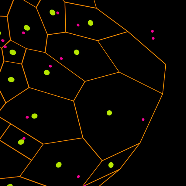
This node creates a 2D Voronoi diagram from the input points. If you’d like to know more about Voronoi intrinsic properties, check out the Wikipedia article!
Properties
| Property | Description |
|---|---|
| Settings | |
| Method | Defines how the position of the Voronoi site is computed. See below for more infos. |
| Expand Bounds | Value added on each axis of the initial input points bounds, used for maths & processes involving bounds. |
| Prune Out of Bounds | Depending on the selected method, the diagram will produce out-of-bounds points (up to ±inf). Enabling this option lets you remove those points from the output. |
Hull Attribute NameBoolean
| If enabled, will flag output Vtx points that lie on the convex hull of the underlying Delaunay diagram.Note that this is not the exact hull, but rather an approximation. |
| Mark Edge on Touch | If enabled, edges that have at least a point on the Hull as marked as being on the hull; as opposed to only be marked as hull edges if both endpoints are on the hull. |
Note that enabling
Prune Out of Boundspoints has a theorical risk of creating more than one finite cluster as a result.
Voronoi site position
| Mode | |
|---|---|
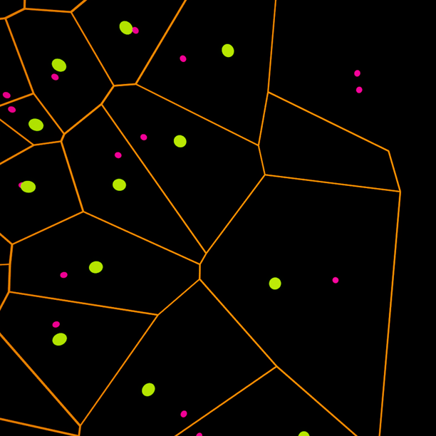 |
Balanced Uses the centroid of the Delaunay site for the point that are outside the bounds, otherwise use circumcenters. Best of both worlds, or worst of both worlds; depending on how you look at it. |
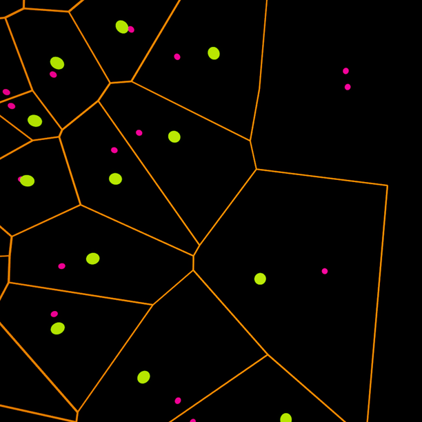 |
Canon (Circumcenter) Uses the circumcenter of the Delaunay triangle. This is the true voronoi algorithm, it guarantees only convex sites. |
 |
Centroid Uses the centroid of the Delaunay site. While more visually pleasing, some concave sites may appear depending on the initial topology. |
Additional Outputs
It may come (very) handy to have access to updated and/or pruned output cell centroid. You can output an modified version of the In points, that better matches the output voronoi cells.
| Settings | |
|---|---|
| Output Sites | If enabled, the node will generate a new output. Sites output have matching ClusterId tags corresponding output Vtx data. |
| Prune Open Sites | If enabled, open (or incomplete) voronoi site will be pruned. This is especially useful if you intend to find individual & valid cell contours. |
Open Site Flagbool
| If the above is disabled, sites matching incomplete or open voronoi sites will be flagged with a boolean attribute. |
Note that canon Voronoi sites are guaranteed to be convex; so if you’re using find contour, you can safely prune concave contours!
Projection Settings
The projection settings control how the point position is translated to a 2D space before the graph is computed; and how this projection will translate back to the original space, if relevant.
| Property | Description |
|---|---|
| Projection Normal | Normal vector of the plane used for projection. By default, the projection plan normal is Up; so the graph is computed over the X Y plane. |
| Local Projection Normal | If enabled, uses a per-point projection vector. |
| Local Normal | Attribute ti read normal from, |
Local projection normal is very powerful but can also be very clunky to use – it’s very easy to end up with singularities that will prevent the graph from being properly computed.